Application note ·
Why 2D X-ray misses prismatic-cell overhang faults – and what 100% inline 3D CT changes for LFP and ESS cell lines
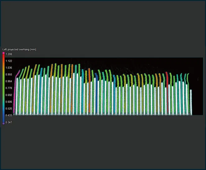
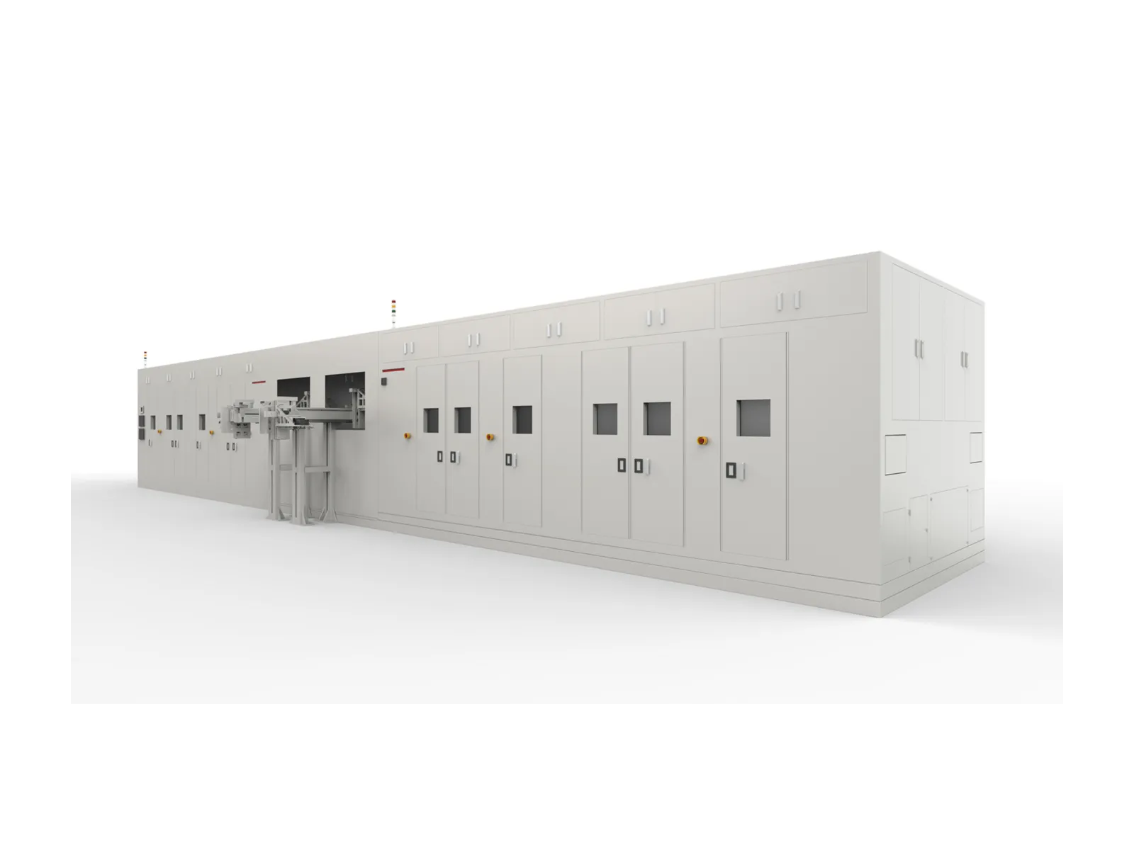
The Royma RMLCT7500 inline gantry CT inspects every prismatic cell in 3D at line speed. It measures electrode overhang at the cell corners to a resolution below 30 µm, at up to 36 parts per minute depending on cell thickness and inspection points. For LFP and ESS cell lines, this replaces sampled laboratory checks and ambiguous 2D X-ray images with a 100% inline measurement.
3D CT separates the layers that 2D X-ray stacks on top of each other
A prismatic cell holds dozens of thin anode and cathode layers. A 2D X-ray image is one projection through all of them at once. At the corners, where the anode must overhang the cathode, the electrode edges overlap in that projection.
Two errors follow from this geometry. Where overhanging edges line up in the beam direction, they merge into one line and hide a real fault. Where a sound stack is slightly offset, it can throw a shadow that looks like an overhang defect. Missed failures ship, and false positives scrap good cells or send them to rework.
Computed tomography (CT) removes the ambiguity because it reconstructs each layer in 3D instead of collapsing the stack into one image. Laboratory CT has always shown this clearly, but it is too slow to cover every cell on a production line. The RMLCT7500 brings that clarity to the line.
“With 3D data, you no longer have to hope that the electrodes line up for the camera,” says Gabor Szabo, Sales Director Europe, Royma Europe. “The RMLCT7500 measures each corner of every cell and gives the line a clear GO or NOGO decision.”
A corner scan makes 3D inspection fast enough for 100% inline use
A full-volume CT scan of a complete prismatic cell would not hold line takt. The RMLCT7500 therefore scans only the regions where overhang faults occur:
- a diagonal 45° corner scan for anode/cathode overhang at all four corners
- an edge scan for folded and crinkled electrode edges
- a scan area of 64 × 64 mm per corner, with a report and analysis area of 8 × 8 mm
- 4–8 seconds for two to six corners
The scanning area and the defect types checked are configurable for each cell design. Reconstruction starts while the scan is still running, so the volume is ready for analysis almost as soon as acquisition ends.
The gantry is modular and built from a configurable number of rings. Throughput is sized to the cadence of the line, up to 36 parts per minute depending on cell thickness and inspection points. A plant can therefore start at ramp-up rates and add capacity as volume grows, without changing the inspection method.
Automatic GO/NOGO decisions replace manual slice review
Inline inspection only works if it produces a decision, not a set of images for an operator to interpret. The RMLCT7500 handles the cells, captures the images and reconstructs each corner automatically. Proprietary algorithms then classify every cell as GO or NOGO and write an automatic report.
Two software functions support that decision. An AI-based image enhancement step sharpens the electrode edges on which the measurement depends. An overhang recognition function then turns the enhanced volume into a measured distance at each corner. Royma also develops customised algorithms for a customer’s specific cell design.
The key figures and the inspection scope at a glance:
| Parameter | RMLCT7500 |
|---|---|
| Method | Inline gantry 3D CT, 100% inline, fully automatic |
| Cell type | Prismatic cells for LFP and ESS applications |
| Throughput | Up to 36 parts per minute, depending on cell thickness and inspection points |
| Corner scan | 4–8 s for 2–6 corners; diagonal 45° scan for overhang; edge scan for folded electrodes |
| Scan area | 64 × 64 mm per corner; report and analysis area 8 × 8 mm |
| Resolution | Below 30 µm |
| Features inspected | Anode/cathode overhang at four corners, electrode alignment, electrode-to-shell distance, folded and crinkled edges, punctures and cuts, foreign objects |
| Evaluation | Automatic image capture and reconstruction; reconstruction starts during scanning; AI image enhancement; overhang recognition; automatic GO/NOGO classification and report |
Practical notes for LFP and ESS cell lines
Prismatic LFP and ESS cell lines are ramping up across Europe, India, the US and Japan, and overhang at the corners is a critical feature on each of them. Three points help when planning inline CT for such a line.
First, define the corners and features to be checked per cell design. The number of corners scanned sets the scan time, and the scan time sets the throughput per gantry.
Second, qualify the measurement on your own cells. Repeatability depends on cell thickness and scan time, so Royma confirms resolution and repeatability on customer samples before a line is specified.
Third, plan for the footprint. An inline gantry CT needs more floor space than a 2D X-ray station. In return, you get 3D data and an automatic decision on 100% of production.
“We recommend starting with a test scan of your own cells,” says Gabor Szabo. “It shows what the corner scan measures on your design and which configuration matches your line speed.”
Test scans of your prismatic cells
Royma Europe offers test scans of customer cells on the RMLCT7500, including an evaluation of overhang, alignment and folded edges on your samples. More on battery inspection: Batteries · Inline CT.
Contact: Gabor Szabo, Sales Director Europe, Royma Europe – gabor_szabo@roymatek.eu – +49 15156503316 – www.roymatek.eu
Royma Europe, Leibniz Universität Hannover – Institut für Produktentwicklung und Gerätebau, Gebäude 8143, An d. Universität 1, 30823 Garbsen, Germany.