Applications
Injection moulding.
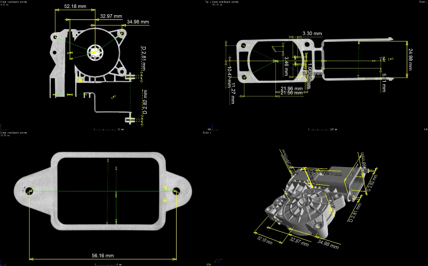
Wall thickness and dimensions.
Inspection tasks
First-article inspection in one scan.
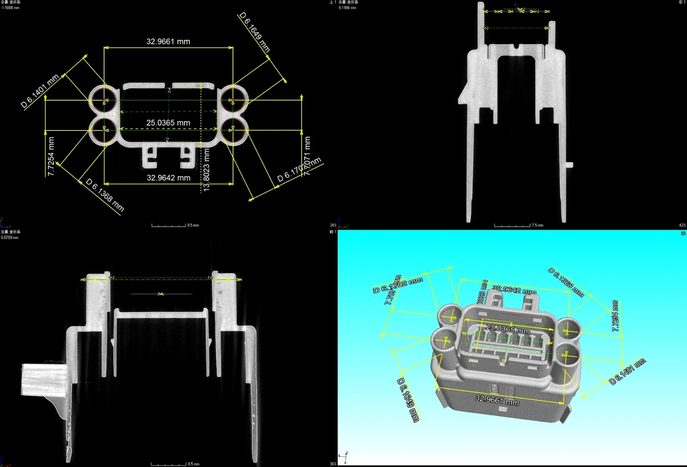
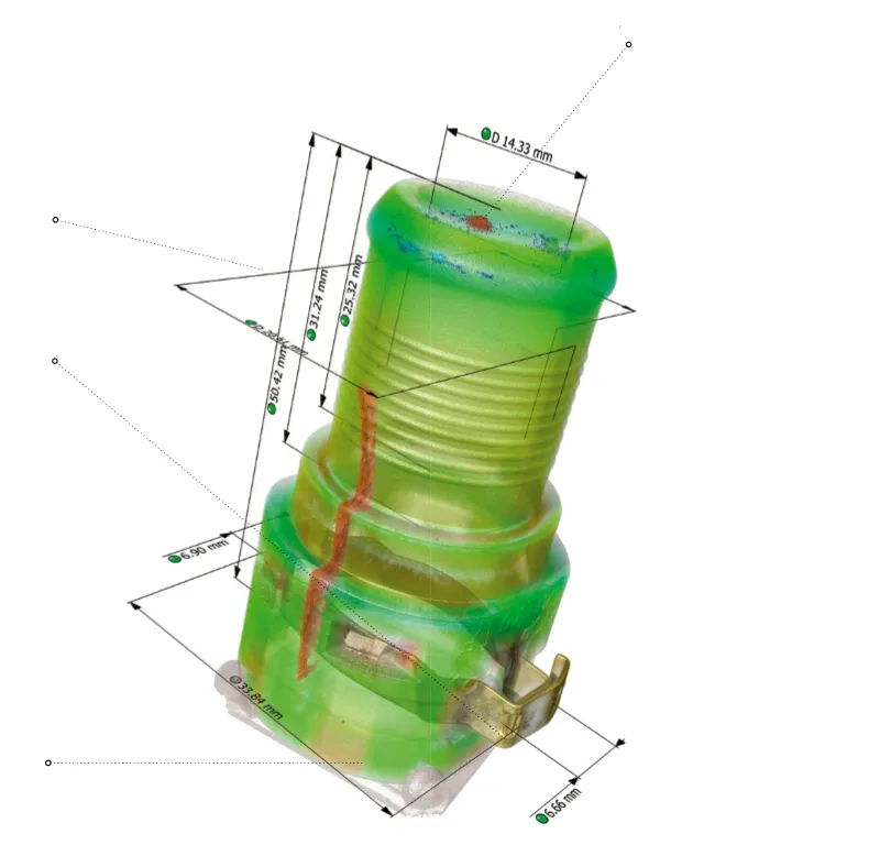
A moulded part is released when every dimension fits. CT measures all of them in one scan, inside and outside, and shows voids and warpage at the same time.
Dimensions and CAD comparison
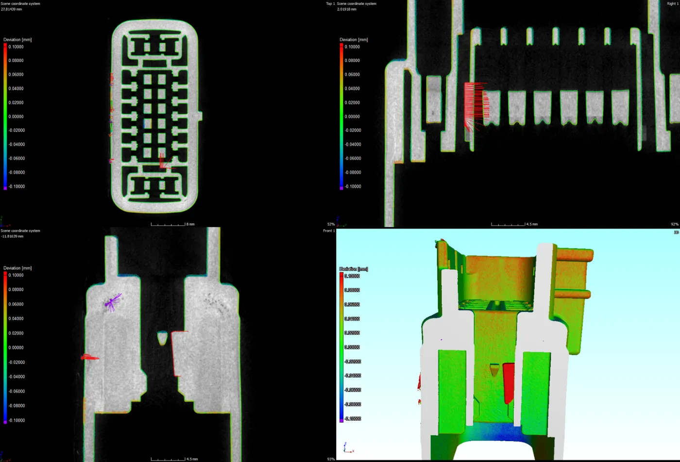
The complete part is compared with the CAD model. Deviations appear as a colour map, which shortens tool correction.
Wall thickness and voids
Wall thickness, sink marks and voids are evaluated across the full volume.
Overmoulded inserts
Pins, contacts and inserts are checked for position inside the plastic.
All these inspection tasks are covered in detail in our injection moulding presentation.
Scan examples
What the data shows.
Systems
Every dimension in one scan.
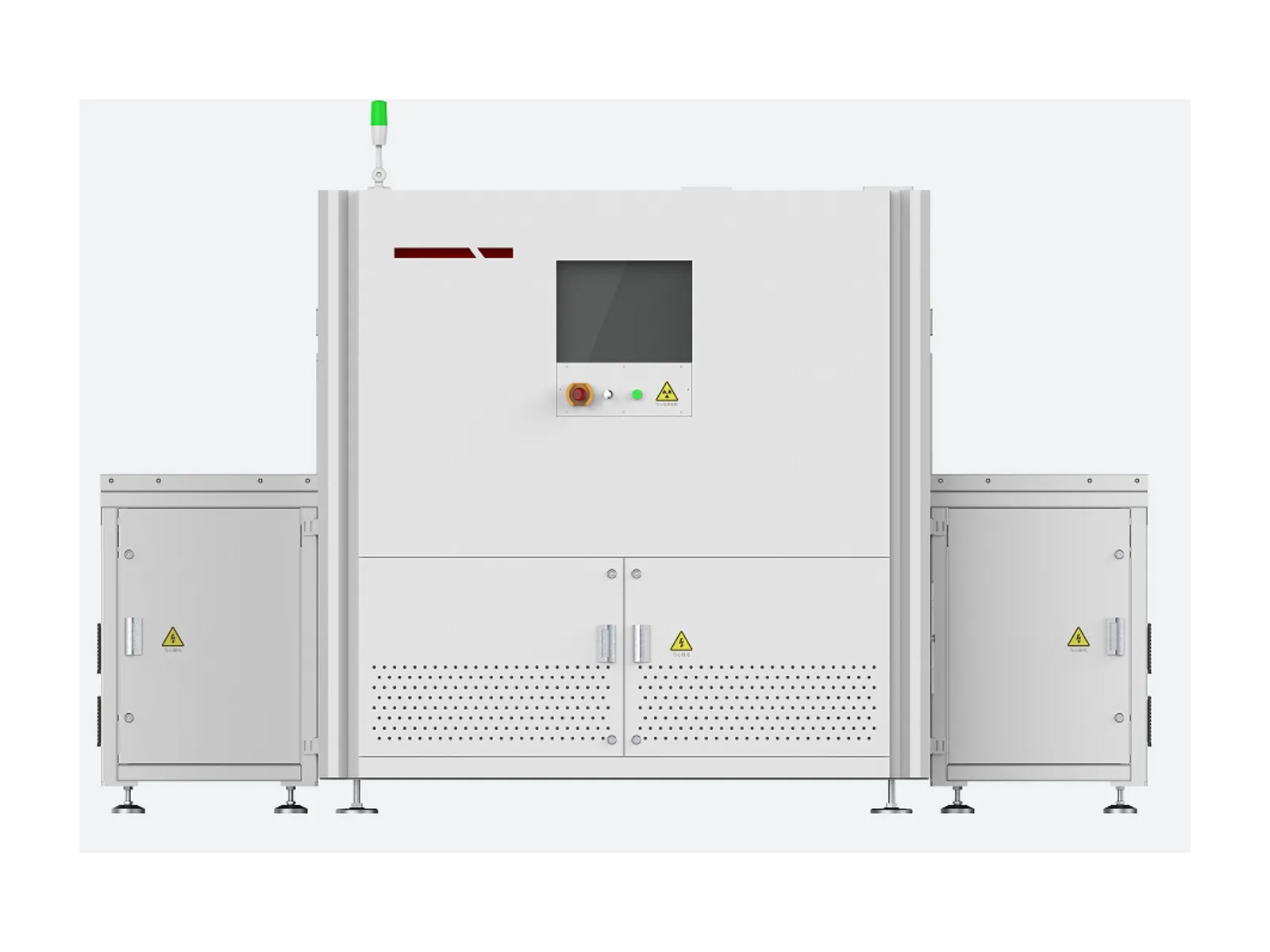
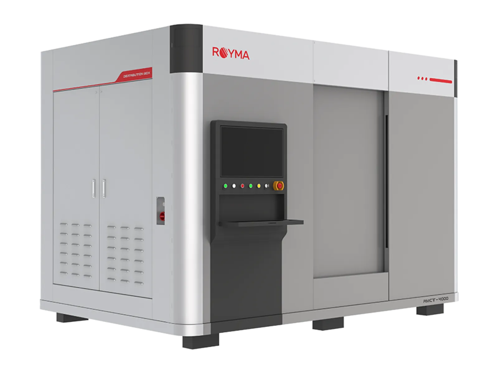
Royma offers CT and X-ray for moulded parts from first-article inspection to series checks. The RMCT4000 scans a moulded part in one pass and measures all its dimensions, inside and outside, on the CT volume, with a 225 or 300 kV microfocus source in three cabinet sizes. Overmoulded inserts, pins and contacts are checked for position inside the plastic in the same data set.
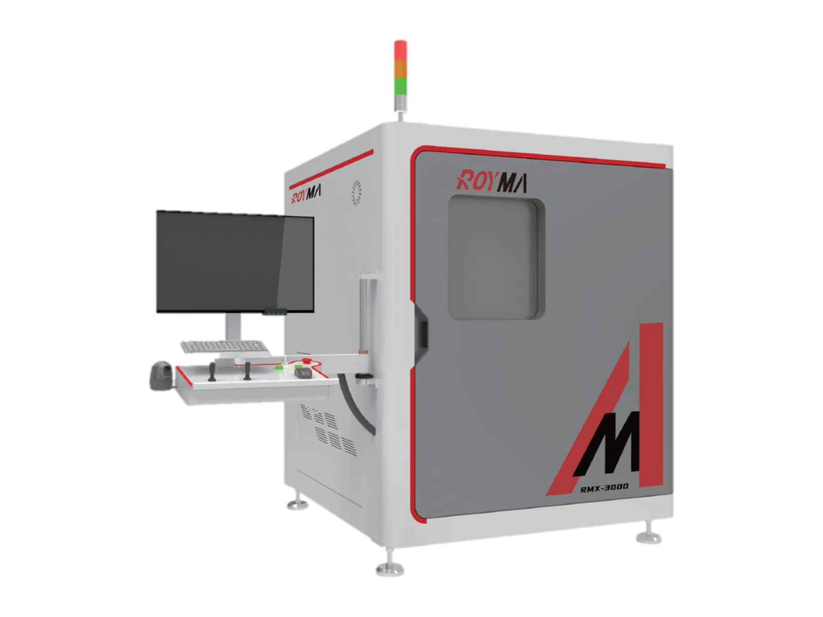
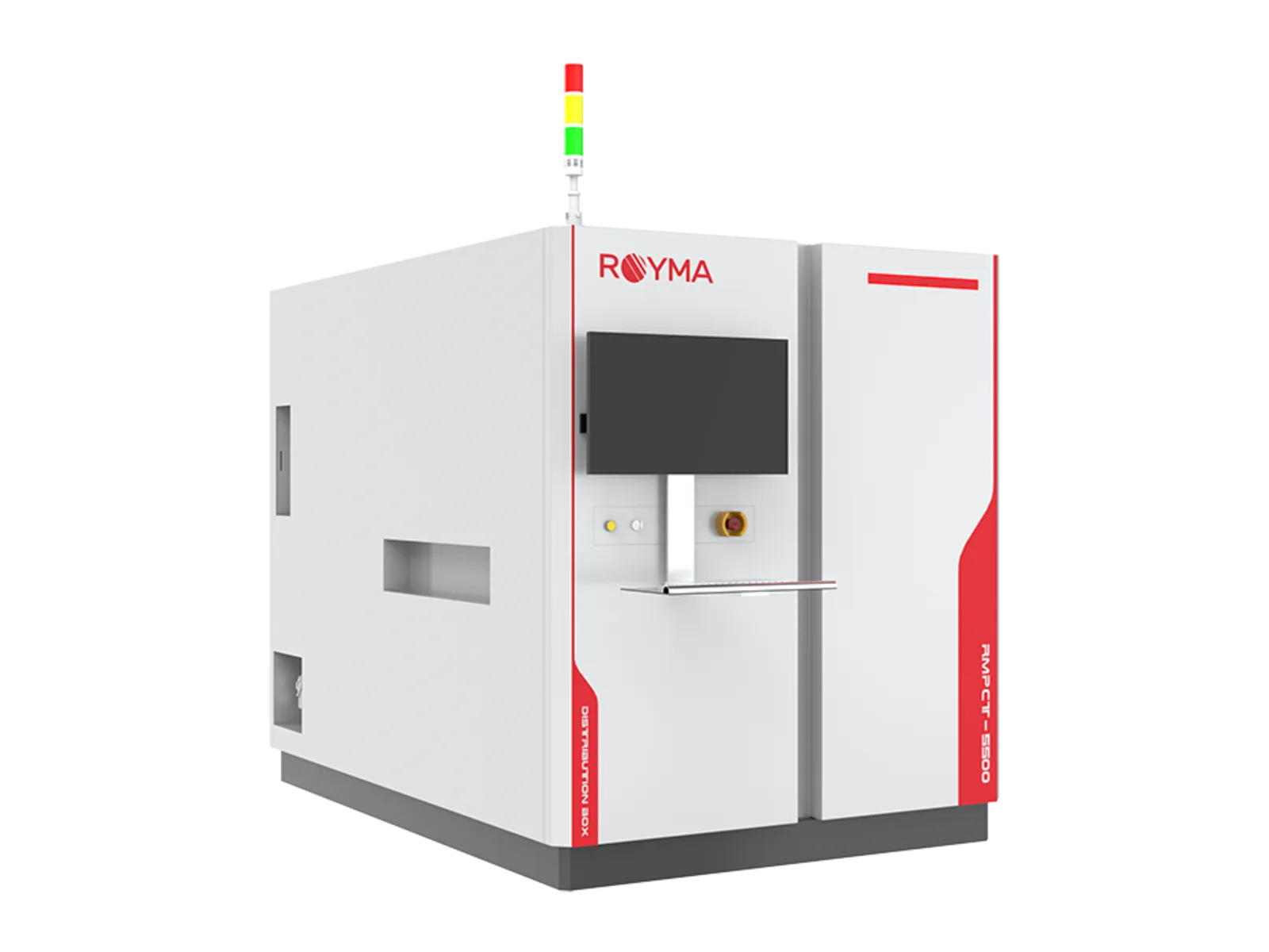
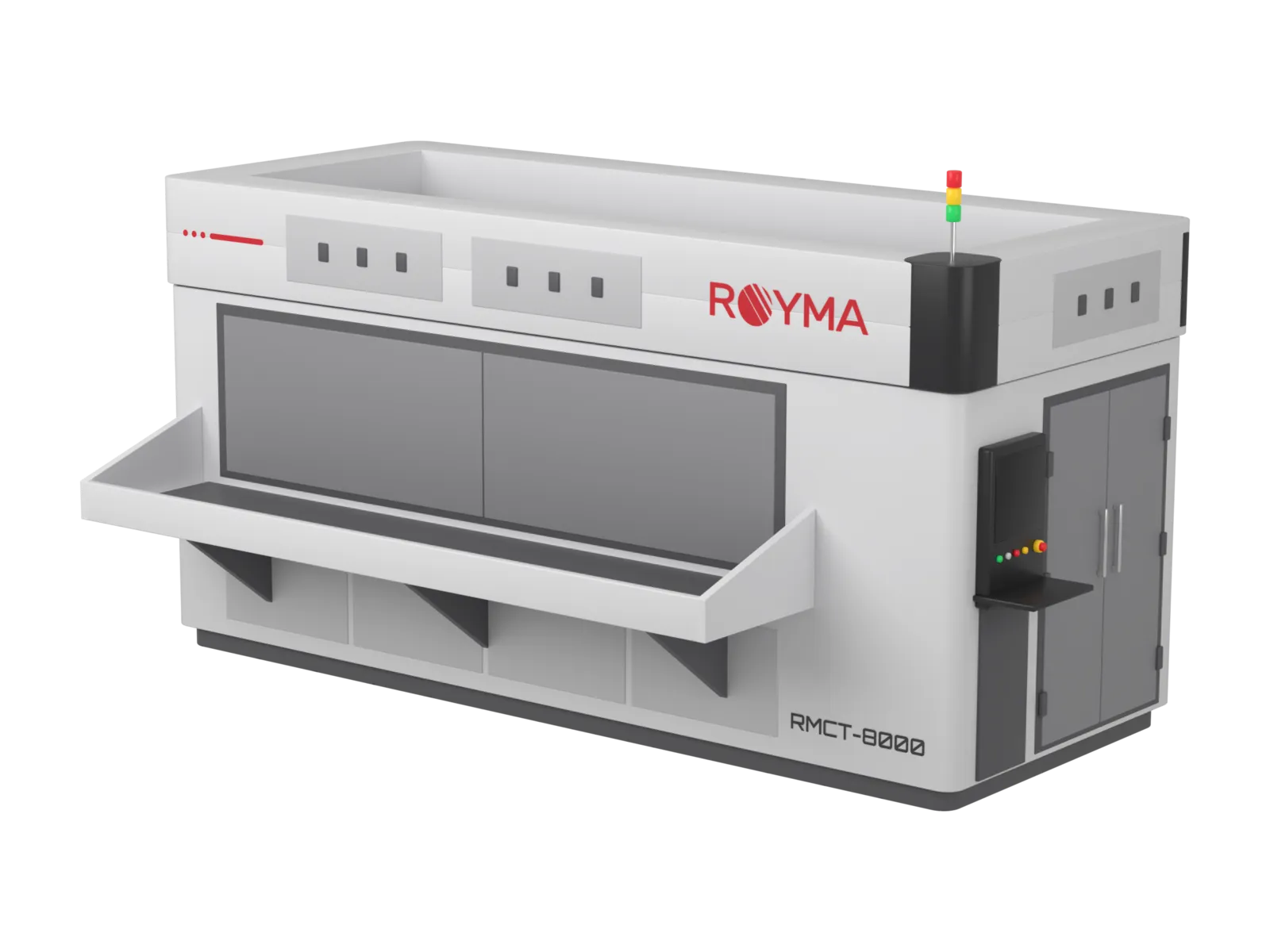
For flat and long mouldings and for parts inspected in the line, the 2D and planar X-ray systems apply: the RMLVX1850 at 3 µm resolution, the RMX3000 with tilted views, the RMPCT5500 with layer-by-layer planar CT for flat assemblies, and the RMCT8000 for parts up to 3500 × 600 mm in one pass. Moulders gain a first-article report from a single scan and a fast check of inserts and dimensions in series.
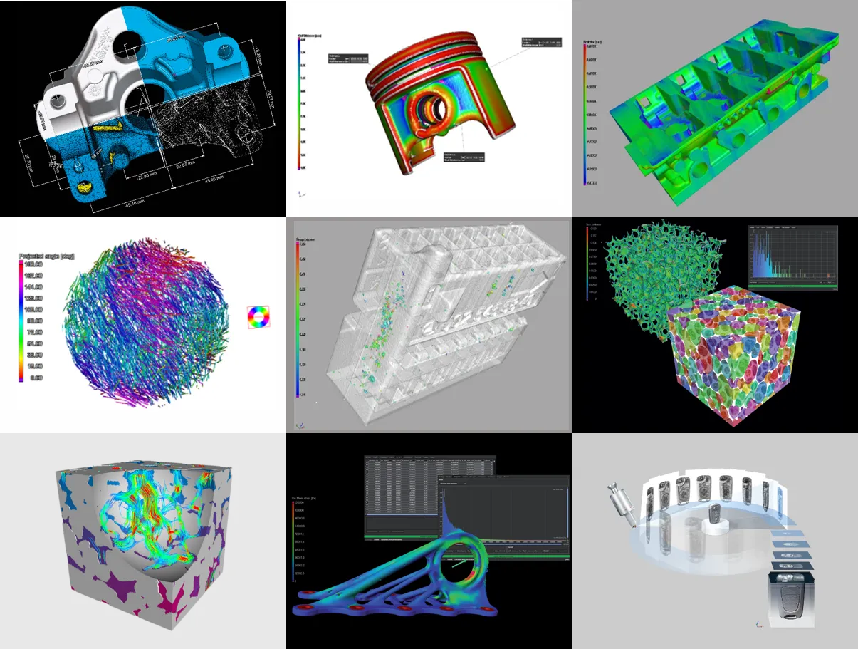
The result is a colour map of the deviation from the CAD model, a wall-thickness map, the sink marks and voids in the volume and the measured values of every feature on the drawing.
In practice
Shorter tool correction, faster release.
At tool trial the nominal-actual comparison shows warpage and shrinkage across the whole part in one image, so the tool corrections are decided from measured deviations. Wall thickness and voids are read from the same volume, and features that no tactile probe reaches, such as undercuts and internal channels, are measured on the CT data.
In series production a saved measurement plan evaluates samples the same way at every check, and overmoulded inserts are verified for position and contact without sectioning the part.
Multi-cavity tools are compared cavity by cavity: each cavity's part is scanned with the same recipe and its deviation map placed beside the others, so a drifting cavity is identified from the data. Weld lines, flash and short shots are documented in the same volume as the dimensions.
Questions
Questions about CT for injection moulding.
- Can CT replace tactile measurement for first-article inspection?
- For most moulded parts, one CT scan delivers every dimension on the drawing, including internal features, as a measurement report and a colour-coded comparison with the CAD model. Tactile measurement remains the reference for individual features where required.
- How are overmoulded inserts checked?
- The metal insert and the plastic are separated in the CT volume, so the position of pins, contacts and inserts inside the part is measured directly.
- What about sink marks and voids?
- Both are shown in the volume with their position and size, together with the wall-thickness map that explains them.
- Which system for large, flat mouldings?
- The RMCT8000 inspects parts up to 3500 × 600 mm in 2D in one pass; the RMCT4000N accepts parts up to ø 575 × 830 mm in 3D.
News