
News ·
Royma brings CAD-matched CT inspection to injection-moulded parts
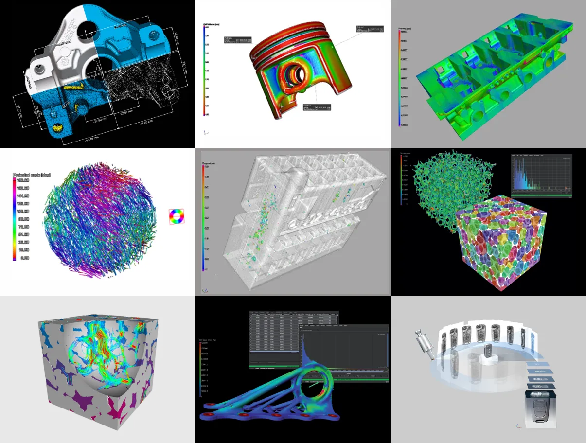
Royma brings CAD-matched CT inspection to injection-moulded parts: its Laboratory CT software takes one computed tomography (CT) scan of a moulded part or a mould pattern and returns GD&T pass/fail results against the CAD golden sample, wall-thickness heat-maps and, where wanted, a STEP surface for reverse engineering. Royma offers the workflow to the moulding plants and toolmakers now bringing new injection-moulding lines into production in Europe.
The evaluation runs on the same volume data that shows the inside of the part. A quality engineer therefore gets internal and external geometry, deviation from CAD and an editable model from a single scan, without a separate 3D scanning or digitising step.
- CAD/PMI import: the CAD golden sample is loaded with its embedded PMI, and the software checks internal and external features and GD&T tolerances automatically.
- Deviation heat-maps: shrinkage, expansion and warping appear as colour maps of the deviation from the CAD model.
- Wall-thickness distribution: colour maps mark critical thin and thick areas across the whole part.
- Reverse engineering: the scanned surface is exported as a STEP file for conversion to NURBS CAD in the customer’s own CAD system.
Pass/fail against the golden sample
Royma’s software reads the PMI already embedded in the customer’s CAD model, so the tolerance scheme the designer defined becomes the inspection plan. Each feature, internal or external, is compared with its nominal value and flagged against its tolerance. Measurements can be placed at defined critical spots, with maximum and minimum threshold checks that return a clear accept or reject. The result is a colour heat-map of the part that shows where it has shrunk, expanded or warped relative to the golden sample.
The software also works directly on the CT voxel data. It defines the true part surface from the volume itself, without first converting the scan into a mesh or a point cloud.
“One scan gives a moulder the complete part: inside, outside and against the CAD,” says Jens Lübbehüsen, Technical Director, Royma Europe. “The same data set answers the dimensional question and shows the internal structure, so there is no second measurement to schedule.”
Wall thickness across the whole part
Thin ribs, bosses and transitions in moulded plastic parts are hard to reach with a caliper or a tactile probe. Royma’s Laboratory CT evaluation measures the wall-thickness distribution over the entire scanned part and presents it as a colour map of the critical areas. Out-of-tolerance zones are visible at a glance.
The multi-viewport metrology environment combines coordinate measurement, regions of interest and nominal/actual comparison in one view. Royma has shown the same evaluation on machined parts and cast components, and the workflow transfers unchanged to moulded plastic housings, connectors and clips. Applications for these part types are listed on the injection-moulding application page.
From scan back to CAD
The same scan also serves reverse engineering. Royma exports the scanned surface as a STEP file, which the customer converts into NURBS CAD in the CAD system of their choice. This applies to moulded parts and to tooling alike: a physical mould or tool pattern, including an inverse mould, can be digitised back into a CAD model.
For a toolmaker, this closes the loop between tool and part. A sampled part can be compared with the golden sample to show where the tool produces shrinkage or warping, and the tool pattern itself can be digitised when no current CAD model exists. The part stays intact and can be scanned again after a tool correction.
“Toolmakers gain a CAD model of the part or the pattern as it really is, not as it was drawn,” adds Lübbehüsen. “That makes tool corrections and replacement tools a data task rather than a manual one.”
What the inspection delivers
Accuracy and evaluation time depend on part size, material and scan settings; Royma states them for each customer part after a test scan rather than as a general figure. Moulding plants commissioning new lines gain one inspection step for first-article approval, tool release and ongoing sampling.
Test scans available
Royma Europe offers test scans of customer parts and mould patterns, with the CAD comparison and wall-thickness evaluation delivered on the customer’s own geometry. Contact Jens Lübbehüsen, Technical Director, Royma Europe, j.luebbehuesen@roymatek.eu, +49 1709782937 – www.roymatek.eu.
Royma Europe, Leibniz Universität Hannover – Institut für Produktentwicklung und Gerätebau, Gebäude 8143, An d. Universität 1, 30823 Garbsen, Germany.
About Royma: Royma Industrial CT develops and builds industrial X-ray and computed tomography systems, from 2D X-ray to horizontal, gantry, planar and inline CT, used to find defects, measure internal geometry and control production quality without destroying the part.