
Application note ·
Royma CT inspection of launcher structures: welds, bond lines and composites
Royma offers CT inspection of launcher structures – welded metallic tanks, thrust-structure joints and composite airframe parts – on its Laboratory CT systems. The same weld, bond-line and composite analyses that Royma applies to aerospace components show porosity, cracks, lack of fusion, delamination and inclusions in 3D, without cutting the part.
Royma Laboratory CT brings one non-destructive data set to three inspection tasks on a launch vehicle: the weld seams of metallic tanks and thrust structures, the bonded joints between composite and metallic parts, and the laminate of the composite airframe itself. For each task the system returns a volume that the quality engineer reads slice by slice or as a 3D rendering, and that stays on file as traceable evidence for the accept or reject decision.
- Welds: porosity, cracks, lack of fusion and lack of penetration, shown inside the seam.
- Bonded joints: glue distribution, voids, delamination and incomplete coverage at composite and multi-material interfaces.
- Composites: metallic inclusions, foreign particles, fibre direction, fibre concentration and fibre distribution.
- Graphite parts: internal porosity that would act as a stress concentration.
Weld seams verified without sectioning
Welded tank domes, cylinder sections and thrust-structure nodes carry their critical defects below the surface. Royma Laboratory CT reveals porosity, cracks, lack of fusion and lack of penetration inside the weld seam and shows where each indication sits along and across the joint. The inspector sees the full seam geometry in the same volume, rather than a single radiographic projection or a cut section.
The scan replaces destructive sectioning of qualification welds. A cross-section shows one plane of one sample; the CT volume shows the whole scanned seam and keeps the part intact for further testing. Weld qualification, process changes and failure analysis all draw on the same type of data set.
“Royma Laboratory CT gives a weld engineer the inside of the seam as a 3D data set – porosity, cracks and lack of fusion located in the joint, with the part still intact,” says Jens Lübbehüsen, Technical Director, Royma Europe.
Bond lines and composite interfaces mapped in 3D
Thrust structures and composite airframe sections join carbon-fibre laminates to metallic fittings with adhesive. Royma Laboratory CT shows the internal glue distribution in these joints and detects voids, delamination and incomplete coverage at the interface. The software calculates the bonded surface area and the coverage percentage of a joint automatically, so a bond line is assessed as a measured result rather than by visual judgement of an edge.
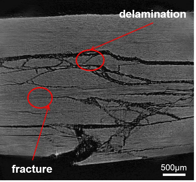
The hero image shows the type of finding this analysis delivers: a CT slice of a fibre-reinforced laminate with delamination between plies and a fracture through the layers. In the volume such indications are followed through the full thickness of the part, which separates an isolated ply separation from a crack network that runs across several layers.
Fibre architecture and inclusions in composite airframe parts
For composite airframe parts, Royma Laboratory CT detects metallic inclusions and foreign particles in the laminate. On fibre-reinforced plastics, including CFRP, the analysis shows fibre direction, fibre concentration and fibre distribution. These are the properties that govern the stiffness and strength of a lay-up and that otherwise call for destructive sectioning or separate laboratory methods.
Graphite parts are covered by the same method. Royma Laboratory CT reveals internal porosity in graphite components, where pores act as stress concentrations under thermal and mechanical load. For powder materials, the software calculates particle count, surface area, volume, sphericity and compactness from the scanned sample.
From qualification samples to series inspection
Royma recommends starting with test scans of representative parts: a qualification weld, a bonded fitting and a composite coupon or section. The first scans set the reference for each joint type and show which indications the CT data resolves on that material and wall thickness. Part size, material and the smallest defect of interest then decide the system configuration and scan parameters; Royma confirms these per part rather than quoting a general detection limit.
As structures move from development lots into series builds, the same scan plan runs on sampled parts, and the results are correlated with welding, lay-up and bonding parameters. Because the CT volume is stored, a later finding in testing or service can be traced back to the inspection data of the original part. “Customers send us their part and receive a scan report that shows exactly what our Laboratory CT finds in their welds, bond lines and laminates,” adds Lübbehüsen.
Inspection tasks at a glance
| Part or joint | What Royma Laboratory CT shows |
|---|---|
| Welded tank and thrust-structure seams | Porosity, cracks, lack of fusion, lack of penetration |
| Bonded composite-to-metal joints | Glue distribution, voids, delamination, incomplete coverage; bonded area and coverage percentage calculated automatically |
| Composite airframe laminates (CFRP) | Fibre direction, concentration and distribution; metallic inclusions and foreign particles |
| Graphite parts | Internal porosity |
| Powder materials | Particle count, surface area, volume, sphericity and compactness |
Detection limits and throughput depend on part size, material and scan set-up and are stated per part after a test scan. More aerospace applications: CT inspection for aerospace and material analysis with CT.
Test scans available
Royma Europe offers test scans of launcher welds, bonded joints and composite parts on its Laboratory CT systems. Contact Jens Lübbehüsen, Technical Director, Royma Europe, j.luebbehuesen@roymatek.eu, +49 1709782937 – www.roymatek.eu.
Royma Europe, Leibniz Universität Hannover – Institut für Produktentwicklung und Gerätebau, Gebäude 8143, An d. Universität 1, 30823 Garbsen, Germany.
About Royma: Royma Industrial CT develops and builds industrial X-ray and computed tomography systems, from 2D X-ray to horizontal, gantry, planar and inline CT.