Application note ·
RMCT10000 delivers a CT scan of the entire sample for titanium additive-manufactured parts before machining
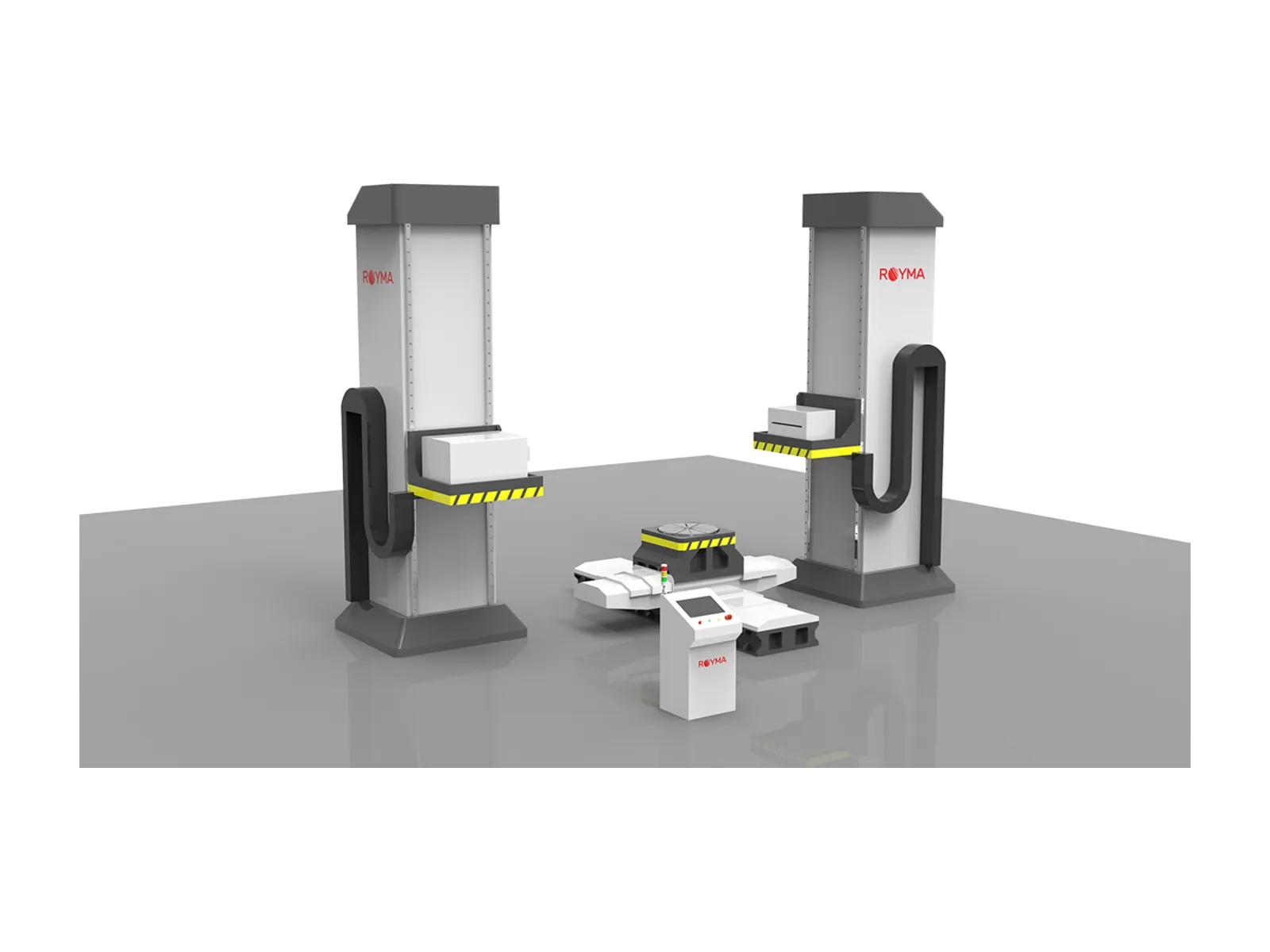
The Royma RMCT10000 delivers a CT scan of the entire sample for titanium additive parts while they are still in the as-built state, before machining removes access to the material. Its linear accelerator (LINAC) X-ray source runs at energies up to 9 MeV, and the system takes samples up to 6000 × 6000 × 3000 mm, so large printed blanks are scanned in one piece rather than as cut coupons.
Wire-arc and powder-based titanium processes are moving from research towards commercial qualification in Europe and North America. This application note is for process engineers and quality leads who produce large titanium parts by additive manufacturing. It describes what a computed tomography (CT) scan of the entire sample shows before machining and how the RMCT10000 is set up for it.
Internal soundness is decided before the first cut
A large additive-manufactured titanium part carries many hours of deposition and expensive material before it reaches the machine tool. Lack-of-fusion voids, gas porosity, cracks and inclusions formed during the build sit inside the part. Machining exposes some of them only when most of the cost has already been spent.
The as-built state is the best moment to look inside. The part still has its full material allowance, and an indication found now can be assessed against the final geometry before any cutting begins. A 2D radiograph shows an indication as a shadow but not its depth, and a sectioned witness coupon describes only the coupon.
Three questions recur when a large printed titanium part is released for machining:
- Soundness: are there voids, porosity, cracks or inclusions, and where do they sit in the volume?
- Position: does any indication lie inside the final machined contour or only in material that will be removed?
- Consistency: is the material along a long deposit path as sound at its end as at its start?
MeV energy and a long geometry for large printed blanks
The RMCT10000 combines a LINAC source with a horizontal CT layout for large, dense components. The source is available with electron energies of 1, 2, 3, 4, 6 or 9 MeV. At 9 MeV the stated penetration is up to 380 mm of steel, the reference material on the data sheet.
“A printed titanium blank is worth most just before machining, and that is when the scan should happen,” says Jens Lübbehüsen, Technical Director at Royma Europe. “The RMCT10000 scans the entire sample in one set-up and shows the inside before the first tool touches it.”
The manipulator works with up to six controlled axes on a granite or cast-iron main frame. A maximum focus-to-detector distance (FDD) of 4000 mm leaves room for long parts and keeps the geometry stable during long scans. Cone-beam scanning covers ø720 × 2600 mm with stitching, and fan-beam scanning covers ø1250 × 2300 mm. Samples up to 2700 × 1400 mm can be placed on the manipulator.
What the scan of the entire sample shows
The CT volume holds the complete internal and external geometry of the as-built part. Porosity, voids, cracks and inclusions appear in 3D with their position in the part. Engineers can slice the volume at any position and along any deposit path, not only at a few cut planes.
Because the scan contains the outer surface, the volume can be aligned with the CAD model of the finished part. An indication can then be classed by whether it lies inside the final contour or in material the machining will remove. That turns a single image into a release decision for the machining step.
“Our customers want one data set that answers soundness and position together,” adds Lübbehüsen. “Scanning the entire sample gives them that data set before the expensive work begins.”
The detail the scan resolves depends on part size, wall thickness and the chosen energy. A large blank scanned in one piece shows coarser features than a small region scanned close to the source. For fine porosity in small coupons and test pieces, Royma Laboratory CT systems complement the RMCT10000.
| Stated figure | RMCT10000 |
|---|---|
| X-ray source | Linear accelerator (LINAC) |
| Electron energy options | 1, 2, 3, 4, 6 or 9 MeV |
| Steel penetration | Up to 380 mm at 9 MeV |
| Largest sample possible to scan | Up to 6000 × 6000 × 3000 mm |
| Sample on manipulator | Up to 2700 × 1400 mm |
| Cone-beam scan (stitched) | ø720 × 2600 mm |
| Fan-beam scan | ø1250 × 2300 mm |
| Maximum FDD | 4000 mm |
| Controlled axes | Up to 6 |
| Main frame | Granite or cast iron |
Practical notes for a first qualification series
Scan the first parts of a new build programme in the as-built state, before stress relief and machining are scheduled. Define the critical zones and the indication classes of your acceptance specification beforehand, so that results are read against them from the first scan. Keep the CAD model of the finished part ready, so that each indication is located against the final contour.
Choose the energy for the thickest titanium path through the part, not the average wall. Where a programme also prints small coupons for material testing, scan a selection of them at higher resolution on a laboratory system. More inspection tasks for printed metal parts are described on the additive manufacturing applications page.
Test scans available
Royma Europe offers test scans of customer titanium additive parts on the RMCT10000 and help in defining the scan set-up for your part sizes. Contact Jens Lübbehüsen, Technical Director, Royma Europe, j.luebbehuesen@roymatek.eu, +49 1709782937 – www.roymatek.eu.
About Royma: Royma Industrial CT develops and builds industrial X-ray and computed tomography systems, from 2D X-ray to horizontal, gantry, planar and inline CT.
Royma Europe, Leibniz Universität Hannover – Institut für Produktentwicklung und Gerätebau, Gebäude 8143, An d. Universität 1, 30823 Garbsen, Germany.