Application note ·
Beyond the electrode stack: CT of top-cover laser welds, safety valves and seal balls on prismatic cells
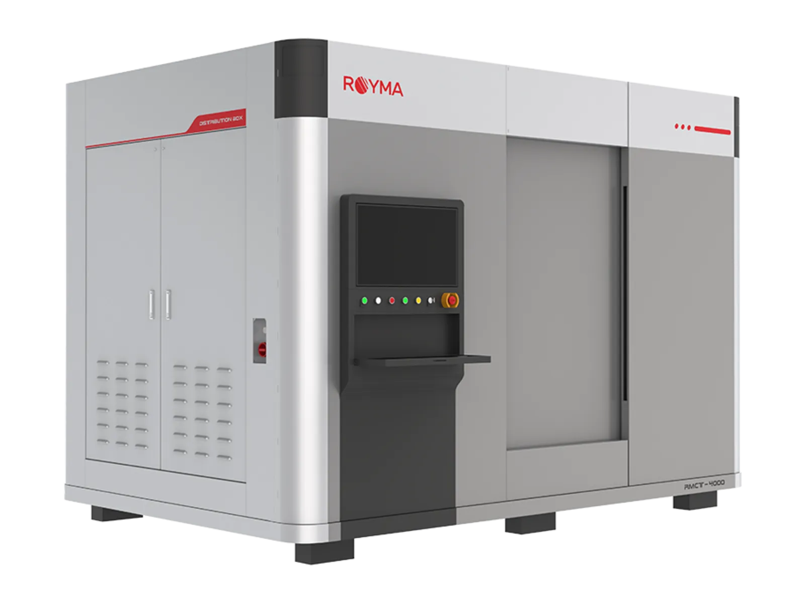
The RMCT4000 laboratory micro computed tomography (CT) machine from Royma Industrial CT inspects the top-cover assembly of prismatic cells in 3D: laser-weld melt depth and pores, safety-valve structure and the seal ball at the electrolyte refill hole. It runs sources up to 300 kV, resolves detail down to 4 µm and takes parts up to 600 × 600 × 800 mm and 100 kg.
This application note is for cell-assembly and joining engineers and quality laboratories at cell and battery-system plants. It shows what a laboratory CT scan reveals on these joints and where the check fits in the process.
Laboratory CT reaches the joints the stack scan leaves out
Inline CT on a cell line is built for the electrode stack. It checks overhang, alignment and foreign objects on every cell at line speed. The top cover is a different inspection task. The laser weld between cover and can, the safety valve and the steel seal ball all sit under aluminium or steel. None of them is visible from outside the finished cell, and all are safety-relevant.
Cutting a cell open answers one question once and destroys the evidence. A laboratory CT scan keeps the cell intact and delivers a volume you can re-slice at any position along the weld. That makes it the tool for the tasks where the answer matters most:
- Weld qualification: verify melt depth and porosity when a new laser parameter set or a new cover design is introduced.
- Failure analysis: locate the weld pore, the misplaced seal ball or the deformed valve in a cell that failed a leak, pressure or abuse test.
- Process audit: check sampled cells from series production after a change of material, supplier batch or welding optics.
“The electrode stack and the top cover are two different inspection tasks,” says Gabor Szabo, Sales Director Europe at Royma Europe. “Inline CT covers the stack on every cell. In the laboratory, the RMCT4000 looks inside the metal joint in detail, which is what a top-cover weld needs.”
One machine covers welds, valves and seals
A laser weld in aluminium or a steel seal ball needs more penetration than the thin electrode foils an inline system is tuned for. The RMCT4000 offers microfocus sources at 100, 190, 225 or 300 kV, in closed- or open-tube versions. An optional dual-source configuration adds a nano CT source to the same cabinet. You then scan a dense cover joint and a fine-structured part without trading resolution against penetration.
The 7-axis manipulator positions the part so that the region of interest, for example one weld seam or the refill hole, sits close to the source. The flat-panel detector has 3072 × 3072 pixels at 139 µm pitch. Parts up to 600 × 600 × 800 mm and 100 kg fit on the stage, so a complete cell, a group of cells or a small module sub-assembly is scanned without being cut down first.
The scan shows melt depth, pores and seal position
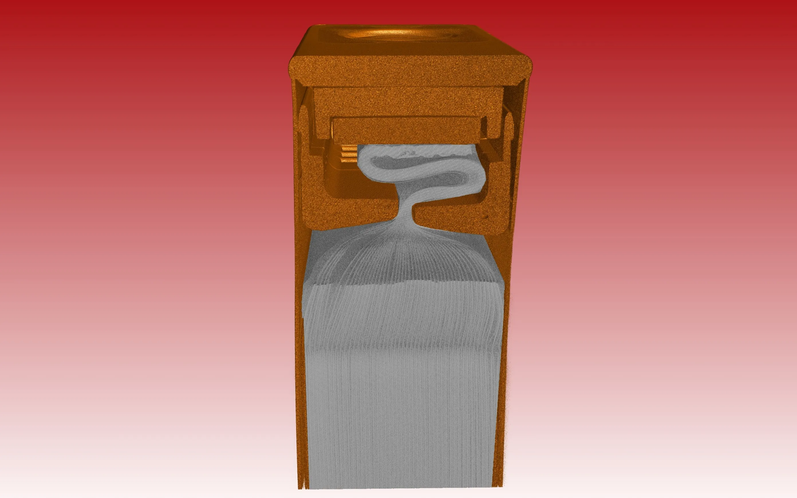
Royma’s application scans on prismatic cells cover the whole cell top. On the top-cover laser weld, the scan shows melt depth along the seam and the pores inside it. It also shows the position of the laser weld between the flexible connection and the boss it joins, and the condition of the flexible-connection joint itself.
On the safety valve, radiography and CT virtual slices show whether the structure is intact and correctly formed. At the refill hole, the scan confirms the position and seating of the steel seal ball. After a puncture experiment, the same method shows the cell’s internal condition without opening it.
Because the result is a 3D volume, a pore is measured rather than described. You can follow a weld seam slice by slice, compare the melt depth at the start, middle and end of the seam, and check the seal ball from any angle.
Practical notes for a laboratory set-up
A laboratory CT check on the top cover is a sampled or investigative step, not a 100% inline test. It sits between the inline electrode-stack inspection that runs on every cell and the module-level checks that follow once cells are joined, such as busbar welds and adhesive coverage. It closes a specific gap: nothing upstream evaluates the top-cover joint in 3D, and nothing downstream can see it once the cell is inside a module.
The finest detail is reached when the region of interest is small and close to the source; a full cell scanned in one piece is imaged at a coarser voxel size than a single weld seam. Weld geometry, cover material and cell format differ from plant to plant. We therefore recommend a test scan of your own cells before scan parameters and sampling plans are fixed. More inspection tasks are described on the batteries applications page.
| Stated figure | RMCT4000 |
|---|---|
| Role | Laboratory micro CT, at-line or sample inspection |
| X-ray source | Microfocus, 100/190/225/300 kV; closed- or open-tube |
| Dual source | Optional, adds a nano CT source |
| Resolution | Down to 4 µm |
| Maximum part size | 600 × 600 × 800 mm |
| Maximum part weight | 100 kg |
| Detector | Flat panel, 3072 × 3072 pixels, 139 µm pixel pitch |
| Positioning | 7-axis manipulator |
| Cell-top tasks | Laser-weld melt depth and pores, weld position, flexible connection, safety valve, seal ball, puncture tests |
Royma Europe offers test scans of customer cells and top-cover samples on the RMCT4000. Contact Gabor Szabo, Sales Director Europe, Royma Europe, gabor_szabo@roymatek.eu, +49 15156503316 – www.roymatek.eu.
Royma Europe, Leibniz Universität Hannover – Institut für Produktentwicklung und Gerätebau, Gebäude 8143, An d. Universität 1, 30823 Garbsen, Germany.