Application note ·
Module-level CT for gigafactory module and pack lines: glue coverage, busbars and cell position at line speed
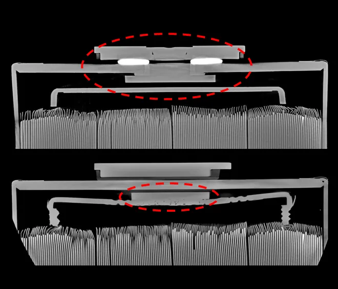
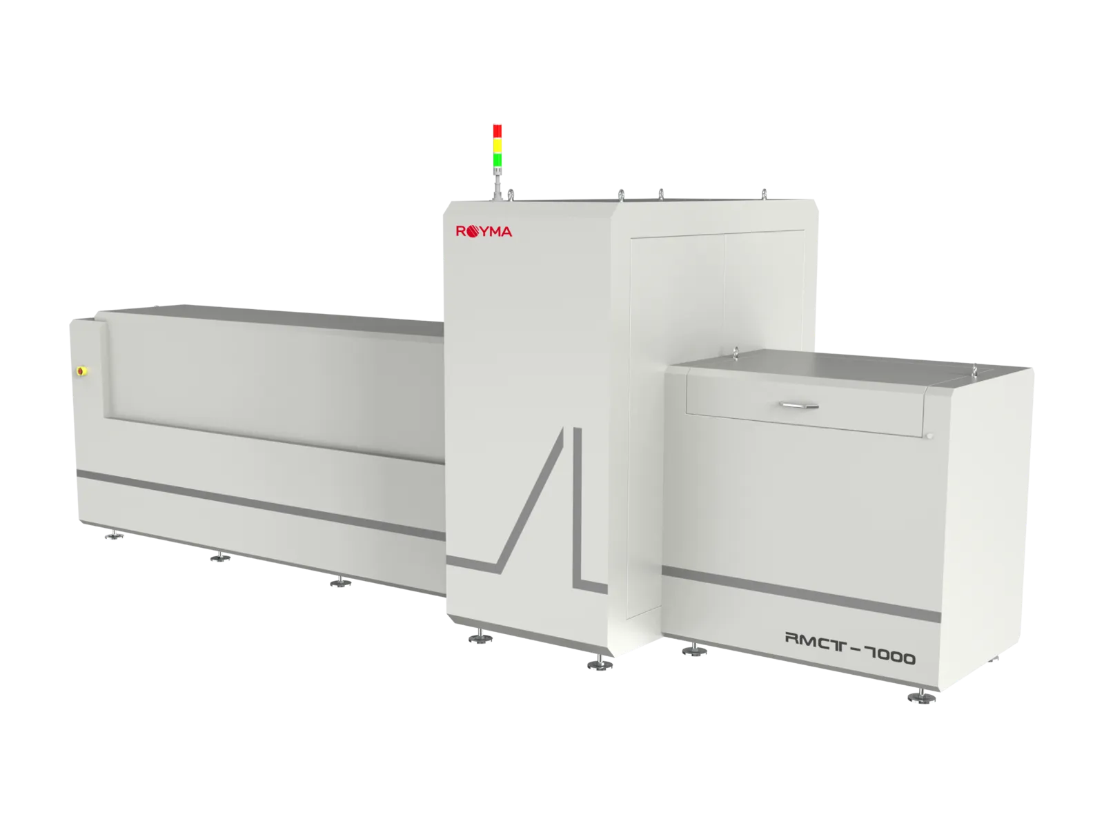
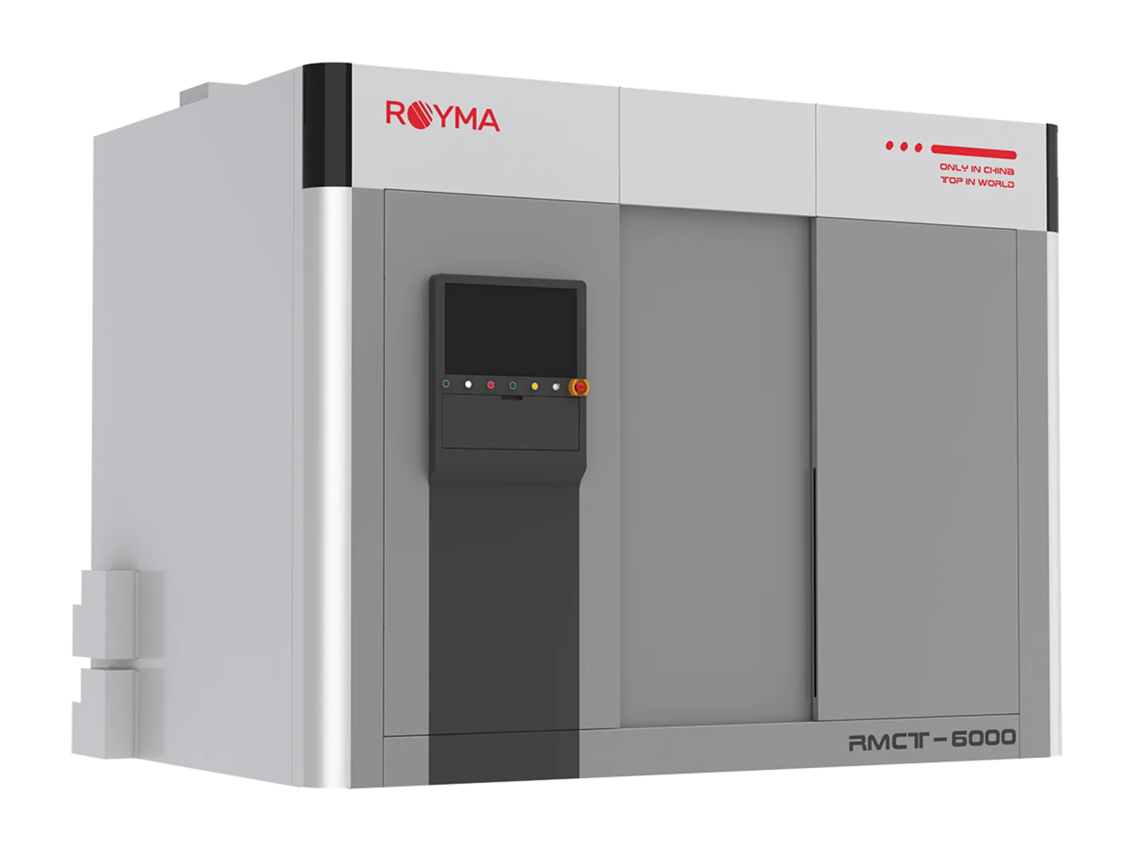
Royma Industrial CT inspects complete battery modules and pack sub-assemblies with computed tomography (CT), without cutting a single module open. The RMCT7000 gantry CT works at-line or inline and, in its large-workpiece configuration, takes parts up to 1010 × 1980 mm and 300 kg at up to 450 kV. For denser pack structures, the RMCT6000D extends the range to 600 kV for the same part size.
This application note is written for quality and process engineers on battery module and pack lines, and for battery engineering teams at automotive manufacturers. It covers what module-level CT shows, which machine fits which task, and how to bring CT from qualification into the line.
CT shows what closes inside the module
Many module faults appear only after the cells are bonded, welded and covered. From the outside the module looks complete. Inside, four questions decide whether it is sound:
- Adhesive: is the glue between cells and cooling plate complete, and where are the gaps?
- Busbar welds: is each weld present and correctly placed, including those hidden below other parts?
- Cell position: does every cell sit where the module CAD says it should, without tilt or offset?
- Foreign objects: has anything been left inside, including in the battery management area?
2D X-ray projects every layer of a module into one image, so a glue gap and an overlapping part can look the same. Destructive teardown answers the question for one module and destroys it. CT answers it in 3D for every module that is scanned, and the module stays intact.
The RMCT7000 keeps the module lying flat
A battery module is long, heavy and flat. The RMCT7000 is a gantry CT: the part rests while the X-ray source and detector rotate around it. The module is scanned lying as it lies on the line, without tall fixtures or a rotary table.
The standard at-line and inline configuration uses a 200 kV closed microfocus source, 150 W, with a 3072 × 3072 pixel flat panel of 139 µm pixels. It takes samples up to 2000 × 420 × 160 mm, and the length can be adapted for inline machines. Measurement precision is 35 µm, depending on the thickness and material of the object. For complete modules and heavier sub-assemblies, the large-workpiece configuration offers 180, 200, 225, 300 or 450 kV for parts up to 1010 × 1980 mm and 300 kg.
The machine offers circular, segmented and limited-angle scans for 3D data, and a fast 2D mode for quick checks. You choose the mode per inspection task, trading scan time against image quality.
“A CT scan of the whole module shows a module maker what is inside a closed assembly – adhesive, welds and cell position in one data set,” says Gabor Szabo, Sales Director Europe, Royma Europe.
The data turns into pass or fail per cell
For glue inspection, the RMCT7000 software evaluates the adhesive area automatically. It reports a coverage percentage for each cell and marks each cell as OK or not OK against the limit you set. Cell position and spacing are compared with the module CAD. Objects that do not belong in the module are flagged in the volume.
The results are three things a quality engineer can act on at once: a coverage map per cell, a position check against nominal, and a list of foreign objects. Because they are numbers, they can be traced back to dispensing, pressing and welding parameters.
The RMCT6000D takes the denser pack structures
Module inspection is first a penetration task. The beam must pass through aluminium housings, cell cans, busbars and cooling plates. Where a pack sub-assembly is denser than the RMCT7000 range covers, the RMCT6000D uses a mini-focus source from 225 to 600 kV. It takes parts up to 1010 × 1980 mm and 300 kg, the same maximum part size as the RMCT7000 large-workpiece configuration.
| Machine and configuration | X-ray source | Maximum part | Further stated figures |
|---|---|---|---|
| RMCT7000, standard at-line / inline | Closed microfocus, 200 kV, 150 W | 2000 × 420 × 160 mm, length adaptable for inline | Flat panel 3072 × 3072 px, 139 µm; measurement precision 35 µm, depending on thickness and material |
| RMCT7000, large workpiece | 180 / 200 / 225 / 300 / 450 kV | 1010 × 1980 mm, 300 kg | Horizontal mechanical system |
| RMCT6000D | Mini-focus, 225–600 kV | 1010 × 1980 mm, 300 kg | Flat panel and line detector |
From qualification scans to the inline station
Because the module never changes orientation, the same scan runs in the laboratory on sampled modules or as an inline station with automated loading. For a new module line, Royma recommends scanning every module of the first builds to set the adhesive, weld and position baseline. During ramp-up, a defined share per shift is scanned and the CT results are correlated with the process parameters. The line then moves to at-line or inline scanning, evaluated automatically against the qualified baseline.
The RMCT7000 is supplied in a full X-ray protection cabinet with safety lock and CE certification, with X-ray leakage below 0.5 µSv/h.
“Four numbers decide the configuration: the largest part, the densest path through it, the smallest defect to be found, and the cycle time available,” adds Szabo. “We evaluate customer modules against exactly those four before we propose a machine.”
Test scans of your modules
Royma Europe offers test scans of customer modules and pack sub-assemblies on the RMCT7000 and RMCT6000D, with an evaluation of glue coverage, weld presence and cell position.
Contact: Gabor Szabo, Sales Director Europe, Royma Europe · gabor_szabo@roymatek.eu · +49 15156503316 · www.roymatek.eu
Royma Europe, Leibniz Universität Hannover – Institut für Produktentwicklung und Gerätebau, Gebäude 8143, An d. Universität 1, 30823 Garbsen, Germany.